It’s Winter but Transceiver Engineers Don’t Hibernate

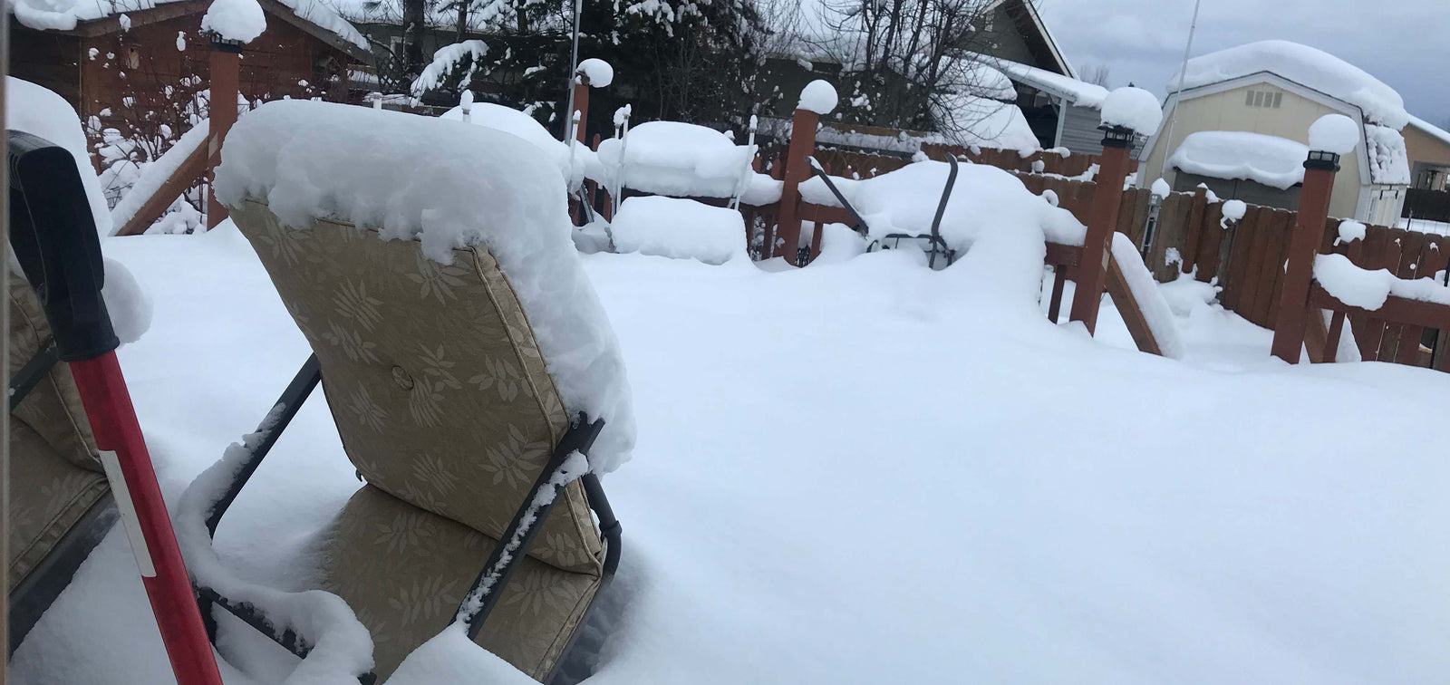
Like many of you around the world, we in north Idaho in the United States are handling our share of snow and ice. We are happy to just keep the walks shoveled and to see the plows come through. Maybe not so happy about the berm the plow leaves at the bottom of the driveway, though.

Getting outside would be nice, but we’re pretty busy inside with PreppComm’s affairs. Our assembler is back after a well-deserved Christmas break. She tackles the multi-facet work of assembling: organizing kits, building transceivers and GO Bags, testing, keeping track of inventory and a plethora of other details, and carefully packing boxes and dropping them off for shipment all over North America and the rest of the world. Yes, we have been shipping internationally for several months and have loyal customers in many countries.
So what are PreppComm’s engineers up to? As the saying goes, “I could tell you, but then I’d have to kill you.” Well, actually, one thing I can tell you is that they continue to improve the DMX-40 Morse code transceiver. It’s now enhanced with an increase of up to eight decibels of receiver sensitivity.
I don’t believe engineering took off any noticeable time, so focused are they on improving current products and developing new ones, based on requests from our customers and our long-term product roadmap: customers who want QRP, or Morse code practice to improve their skills, or for preparedness communications in an emergency, or are HF aficionados.

Until recently, our engineers had measured readings with an outdated service monitor, but they recently acquired a spanking new Siglent Digital Storage Oscilloscope. Result: more accurate readings of harmonics in the output and other measurements. Not only a wave display, but accurate digital readouts at the same time!
I will talk about PreppComm’s new cable assembly in a separate post. This new accessory is designed for customers who have been wanting to use the DMX-40 with an external transceiver—it’s called External Mode. You can find the cable assembly on our Products/Accessories page.
Peeking into the lab, you would find the engineers bent over circuit boards as they solder surface-mounted components. It’s a challenge. They have to use a microscope. Those parts measure somewhere between the size of a speck of sand and a grain of rice. Just a

breath blows them away, likely never to be found. So at this stage of development, to speed up the process, one engineer picks the parts and returns extras, per the bill of materials (BOM), and the other painstakingly removed them from the tape, carefully positions them, and solders them. At times, the part goes flying off of the tweezers into outer space! Zing! This process is a far cry from what happens in factory production, which I’ll explain.
If ever you have had cause to open up a device and examine a circuit board with its slew of parts, you might have wondered, “How did they build this?” It’s a fascinating. process. When a product moves into production on the assembly line, surface mount technology (SMT) revs into high gear at the factory. While it moves fast, the risks of defects increase. The surface-mount devices have arrived to the printed circuit board producer from their various manufacturers, packaged on reels and ready for the next step. Hold on. I’m a little ahead of myself, because first a stencil masks the product empty circuit board and squeegees on solder paste in the solder pads for the parts.

There are two kinds of pick-and-place machines, for different types of components: Chip shooters and flexible placers. Chip shooters rapidly place smaller parts at 20,000 to 80,000 per hour—in the exact position where they belong. Flexible placers load larger integrated circuits or connectors, for example, at a slower pace— to ensure accuracy—at speeds of 6,000 to 40,000 per hour! That’s something our engineers definitely cannot do in the lab. (While we never measured our speed, it is more like 10 or 20 per hour!) Inspection and rework take place along those busy production lines. Technicians monitor each step along the way, inspecting and reworking the product along the lines. Once all the parts have been placed, the printed circuit boards are moved into a very special reflow oven, which ramps up the temperature to a high value, causing the solder paste to melt, and to thus hold all the parts in place, electrically connected to the board. Finally, through-hole parts are manually soldered in place, and—presto!— a new batch of radio boards is ready to forward to our workshop.
Back here, in the northern United States, we anxiously await that tracking number, that announcement that within days (we hope) those newly manufactured boards will land at our factory, ready to be programmed and assembled into products, then tested to ensure they meet the product specification, for pending and future orders. Snow or not, our priority is to get your shipment out to a carrier so that you can begin having fun with your text-to-Morse-code transceiver!
